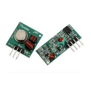

Description: This wireless transmitter and receiver pair operate at 315Mhz. They can easily fit into a breadboard and work well with microcontrollers to create a very simple wireless data link. Since these are only transmitters, they will only work communicating data one-way, you would need two pairs (of different frequencies) to act as a transmitter/receiver pair.
Note: These modules are indiscriminate and will receive a fair amount of noise. Both the transmitter and receiver work at common frequencies and don’t have IDs. Therefore, a method of filtering this noise and pairing transmitter and receiver will be necessary. The example code below shows such an example for basic operation. Please refer to the example code and links below for ways to accomplish a robust wireless data link.
![]()
Application environment
Remote control switch, receiver module, motorcycles, automobile anti-theft products, home security products, electric doors, shutter doors, windows, remote control socket, remote control LED, remote audio remote control electric doors, garage door remote control, remote control retractable doors, remote volume gate, pan doors, remote control door opener, door closing device control system, remote control curtains, alarm host, alarm, remote control motorcycle remote control electric cars, remote control MP3.
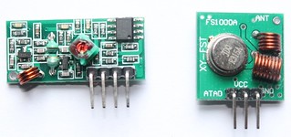
Receiver module parameters
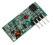
1. Product Model: MX-05V
2. Operating voltage: DC5V
3. Quiescent Current: 4mA
4. Receiving frequency:315Mhz
5. Receiver sensitivity:-105DB
6. Size: 30 * 14 * 7mm
Technical parameters of the transmitter module
1. Product Model: MX-FS-03V
2. Launch distance :20-200 meters (different voltage, different results)
3. Operating voltage :3.5-12V
4. Dimensions: 19 * 19mm
5. Operating mode: AM
6. Transfer rate: 4KB / S
7. Transmitting power: 10mW
8. Transmitting frequency: 315Mhz
9. An external antenna: 25cm ordinary multi-core or single-core line
10. Pinout from left → right: (DATA; VCC; GND)
![]()
An example:
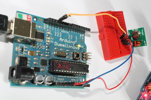
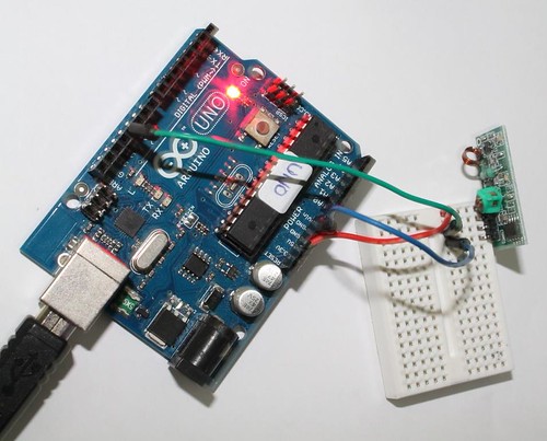
In this example, receiver and transmitter modules are connected separately to two Arduino boards. The transmitter data pin is connected to Pin 12 of Arduino and the receiver data pin is connected to Pin 11 of Arduino.
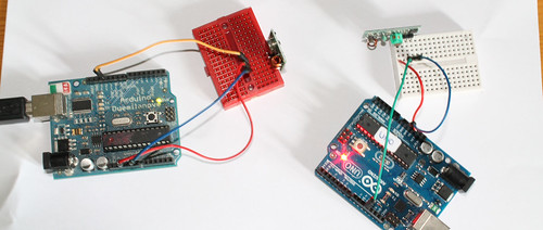
Connecting transmitter module to Arduino:
Sketch:
Download library(Virtual wire)
Connecting receiver module to Arduino: See all the images on flickr Sketch:
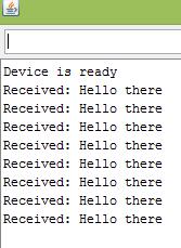
Output:
The transmitter sends a string “Hello there” and the receiver receives it and displays on serial monitor.
Related links:
![]()
🛠️ Dive into our collection of DIY Kits, 🔊 Audio Amplifiers, Digital Scoreboards, FM transmitters, and more!
🎶 Explore endless possibilities at our new store.